|
FG Camera Library
|
|
|
FG Camera Library
|
|
The VisionSensor PV is a compact programmable Linux camera. Unlike the VisionCam, it does not provide a "Real Time Communication Controller" (RTCC). Sensor trigger and the integrated LED are controlled by this libraray, while the digital I/Os are controlled by the VisionBox Interface Library.
There are two hardware generations:
The VisionSensor PV3 can also be connected to an I/O Expansion hardware which provides additional I/Os and the "Real Time Communication Controller".
Also take a look at the Sensors page for information about available sensors for each platform.
The function FG_set_trigger_mode() is used to configure one of the trigger modes:
Example:
The VisionSensor PV / PV2 uses a fixed connection from digital input IN0 to the sensor in hardware triggered mode. Therefore, no additional initialization code is necessary. The rising edge will be used.
The VisionSensor PV3 provides the following special features for configuration of the trigger signal:
| Property name | Description | Version requirements | |
|---|---|---|---|
| FPGA | Library | ||
| TriggerLine | Selects the trigger signal in hardware triggered mode. IN1 is not available when using FrameTriggerMode 2 and 3. 0: IN0, rising edge (default) Additional values for the VisionSensor PV3 with I/O Expansion:1: IN1, rising edge 2: IN0, falling edge 3: IN1, falling edge 4: IN0, rising and falling edge 5: IN1, rising and falling edge 6: IN0 + IN1, rising and falling edges 100...115: VIB::Multiplexer output line 0...15, rising edge 200...215: VIB::Multiplexer output line 0...15, falling edge | ≥ 1.0.0.68 for values ≥ 2, ≥ 1.0.0.75 for values ≥ 100, | ≥ 1.3.0.0 |
| TriggerDivider | 1...65536: divider value (default: 1) | ≥ 1.0.0.68 | |
| TriggerDelay | 0...6700000: delay value in micro-seconds (default: 0)
| ≥ 1.0.0.85 | ≥ 1.7.1.0 |
Example:
If the sensor is used in Line scan mode, an additional frame trigger signal can be configured using the special feature FrameTriggerMode.
The operating mode of the integrated LED unit and the exposure output signal can be controlled by software or by a physical mode switch (VisionSensor PV / PV2 only):
The position of the physical switch is used for mode selection unless it's overwritten by software. For software mode control, use the special feature StrobeMode. The value for this parameter is equal to the switch position for modes 0...2:
| Switch position | Software control (StrobeMode) | Integrated LED | Digital output OUT<i> |
|---|---|---|---|
| 0 | 0 | Enabled | Controlled by VIB::DigitalOutput |
| 1 | 1 | Off | Sensor exposure signal |
| 2 | 2 | Off | Controlled by VIB::DigitalOutput |
| - | 3 | Enabled | Sensor exposure signal |
| - | -1 | Controlled by switch | |
| Property name | Description | Library |
|---|---|---|
| StrobeMode | Sets the operating mode for the integrated LED and the exposure signal for replacing the physical mode switch. -1...3: strobe mode (default: 2 if no switch is present)
| ≥ 1.2.0.0 |
| StrobeOutput | Selects the digital output line for the external exposure signal. 0...<i>: index of digital output signal OUT<i> (default: 0)
| ≥ 1.2.3.0 |
Example:
The LED current can be adjusted for the following hardware:
The LED current is controlled by the following special feature:
| Property name | Description | Version requirements | |
|---|---|---|---|
| FPGA | Library | ||
| LedCurrent | LED current in percent, the minimum value depends on the LED hardware x...100 Default value for multi-channel LED illumination unit: 100Default value for adjustable ring light: 28 (similar to non-adjustable model) | ≥ 1.0.0.70 (for adjustable ring light only) | ≥ 1.4.0.0 |
| LedDutyCycle | Returns the maximum usable duty cycle in percent (read-only) Multi-channel LED illumination unit: the content of the pointer argument must be initialized with the LED channel. | - | ≥ 1.7.0.0 |
A sequencer can be used to apply different settings to subsequent sensor frames:
The sequencer is configured using special features as follows:
The sequencer is controlled by the following special features:
| Property name | Description | Version requirements | |
|---|---|---|---|
| FPGA | Library | ||
| SequencerStepCount | Number of active Sequencer steps 1...4 (default: 1) | ≥ 1.0.0.70 | ≥ 1.4.0.0 |
| SequencerStep | Selected Sequencer step index for using the following special options: SequencerTriggerMode, SequencerFlashTime, SequencerFlashEnable 0...(SequencerStepCount - 1) (default: 0) | ||
| SequencerTriggerMode | Trigger mode for the selected Sequencer step. This setting is ignored in free run mode: 0: disable sensor trigger for this step, acquire image when the sensor is ready 1: enable sensor trigger for this step (default) | ||
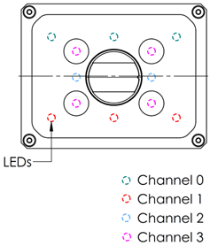
| SequencerFlashEnable | LED illumination unit: a bit field for selecting active LED channels for the selected Sequencer step. 0x0...0xf (default: 0x3 - channel 0+1 for step 0, else 0x0) | ||
| SequencerFlashTime | LED illumination unit: strobe duration for the selected Sequencer step in micro-seconds. 1...16384 (default: 100) | ||
Correlation between acquired images and the used sequencer step can be done in two ways:
image_scan_count equal to the number of sequencer steps. The resulting image will contain the sensor images for all steps after another in memory.The trigger mode can be used to enable or disable the sensor trigger for each sequencer step.
The trigger is activated by default for all steps, so the sensor will wait for a trigger signal (hardware or software trigger). If the trigger mode is disabled for a sequencer step, the sensor will start acquisition as soon as the previous sensor exposure and readout has completed.
Example:
The following example configures the sequencer to capture three frames for each trigger event:
In free-run mode, the sequencer trigger mode setting affects the acquisition as follows:
The following LED parameters can be changed for each sequencer step when using the multi-channel LED illumination unit:
Example:
The optional Liquid Lens hardware is controlled by the special feature Focus:
| Property name | Description | Library |
|---|---|---|
| Focus | DAC value controlling the Liquid Lens focus: 0...255 (default: 128) | ≥ 1.7.0.0 |
Example: