|
VisionBox Interface Library
1.7.15.0 (2026-04-13)
|
|
|
VisionBox Interface Library
1.7.15.0 (2026-04-13)
|
|
This class controls the digital camera trigger output.
Each camera trigger output has two transistors, one for the positive and one for the negative side. Both transistors can be programmed independently. Therefore, the output can be configured in push-pull, open-collector or emitter-follower configuration.
The image below gives a simplified view of the unit:
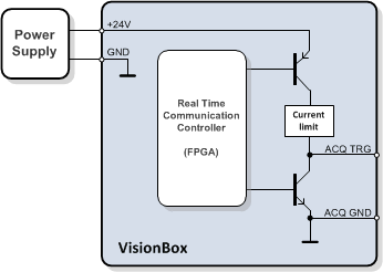
The high-side switch is connected to the power supply voltage of the VisionBox and has a current limiting circuit. For a detailed electrical specification please take a look at the VisionBox Hardware Manual.
The camera trigger output can be connected to different source signals by using the Set() functions, there are two overloaded versions.
The configuration of a trigger output takes the following parameters:
Public Types | |
| enum | DRIVER_MODE |
| Output driver mode. More... | |
| enum | TRG_SOURCE |
| Camera trigger source. More... | |
Public Member Functions | |
| CameraTrigger () | |
| Default constructor for the device object. | |
| bool | GetNumberOfOutputs (unsigned int &NumberOfOutputs) |
| Returns number of output channels. | |
| bool | Reset () |
| Resets the device to default settings. | |
| bool | Set (unsigned int Channel, TRG_SOURCE Source, bool TrgPOff=false, bool TrgPOn=true, bool TrgNOff=false, bool TrgNOn=false) |
| Sets trigger output for the specified channel. | |
| bool | Set (unsigned int Channel, TRG_SOURCE Source, DRIVER_MODE DriverMode, bool Invert=false) |
| Sets trigger output for the specified channel. | |
| bool | SetAll (TRG_SOURCE Source, bool TrgPOff=false, bool TrgPOn=true, bool TrgNOff=false, bool TrgNOn=false) |
| Sets the trigger output for all channels simultaneously. | |
| Public Member Functions inherited from VIB::iDevice | |
| bool | Close () |
| Closes a device. | |
| iDevice (const iDevice &device) | |
| The copy constructor makes a copy of the existing device object. | |
| bool | isOpen (bool &state) |
| Returns the open state of a device object. | |
| bool | Open (unsigned int Index=0) |
| Opens a device. | |
| iDevice & | operator= (const iDevice &device) |
| The assignment operator makes a copy of the existing device object. | |
| virtual | ~iDevice () |
| Deletes the device object. | |
Output driver mode.
Camera trigger source.
| VIB::CameraTrigger::CameraTrigger | ( | ) |
Default constructor for the device object.
The device must be opened with Open() before it can be used.
| bool VIB::CameraTrigger::GetNumberOfOutputs | ( | unsigned int & | NumberOfOutputs | ) |
Returns number of output channels.
| NumberOfOutputs | Number of outputs |
true for success, use VIBSystem::GetLastErrorString() for an error description| bool VIB::CameraTrigger::Reset | ( | ) |
Resets the device to default settings.
All trigger outputs are configured to high impedance state.
true for success, use VIBSystem::GetLastErrorString() for an error description| bool VIB::CameraTrigger::Set | ( | unsigned int | Channel, |
| TRG_SOURCE | Source, | ||
| bool | TrgPOff = false, | ||
| bool | TrgPOn = true, | ||
| bool | TrgNOff = false, | ||
| bool | TrgNOn = false ) |
Sets trigger output for the specified channel.
The default parameters are set for emitter-follower configuration. The following table shows useful parameter combinations:
| Driver configuration | Polarity | Parameter | |||
|---|---|---|---|---|---|
| TrgPOff | TrgPOn | TrgNOff | TrgNOn | ||
| Push-Pull | normal | false | true | true | false |
| inverse | true | false | false | true | |
| Emitter-follower | normal | false | true | false | false |
| inverse | true | false | false | false | |
| Open-collector | normal (low-active) | false | false | false | true |
| inverse (high-active) | false | false | true | false | |
| Channel | Channel number, 0 ... (GetNumberOfOutputs() - 1) |
| Source | Trigger source signal |
| TrgPOff | High side switch activity for low input signal |
| TrgPOn | High side switch activity for high input signal |
| TrgNOff | Low side switch activity for low input signal |
| TrgNOn | Low side switch activity for high input signal |
true for success, use VIBSystem::GetLastErrorString() for an error description| bool VIB::CameraTrigger::Set | ( | unsigned int | Channel, |
| TRG_SOURCE | Source, | ||
| DRIVER_MODE | DriverMode, | ||
| bool | Invert = false ) |
Sets trigger output for the specified channel.
| Channel | Channel number, 0 ... (GetNumberOfOutputs() - 1) |
| Source | Trigger source signal |
| DriverMode | Driver mode |
| Invert | Polarity |
true for success, use VIBSystem::GetLastErrorString() for an error description| bool VIB::CameraTrigger::SetAll | ( | TRG_SOURCE | Source, |
| bool | TrgPOff = false, | ||
| bool | TrgPOn = true, | ||
| bool | TrgNOff = false, | ||
| bool | TrgNOn = false ) |
Sets the trigger output for all channels simultaneously.
The function has the same behaviour as calling Set() an all channels, except that all changes are applied simultaneously.
true for success, use VIBSystem::GetLastErrorString() for an error description