|
VisionBox Interface Library
1.7.15.0 (2026-04-13)
|
|
|
VisionBox Interface Library
1.7.15.0 (2026-04-13)
|
|
This class controls the I/O Scheduler which can store and emit output signals in hard real-time.
The I/O Scheduler is an internal unit which can be used to create output signals with timing based on other trigger events, encoder position, or timer values. The I/O Scheduler is only connected to the Multiplexer.
Each I/O Scheduler contains a buffer (FIFO) which stores entries with desired output values and their trigger activation values. These buffer entries are first pushed by software with no hard real-time requirement. The unit can then read and evaluate values from this buffer without further interaction by software.
The unit has three different counters to provide three different modes of operation. The mode is configured by selecting the counter used for comparison against the next buffer entry (see also SetCompareSource()):
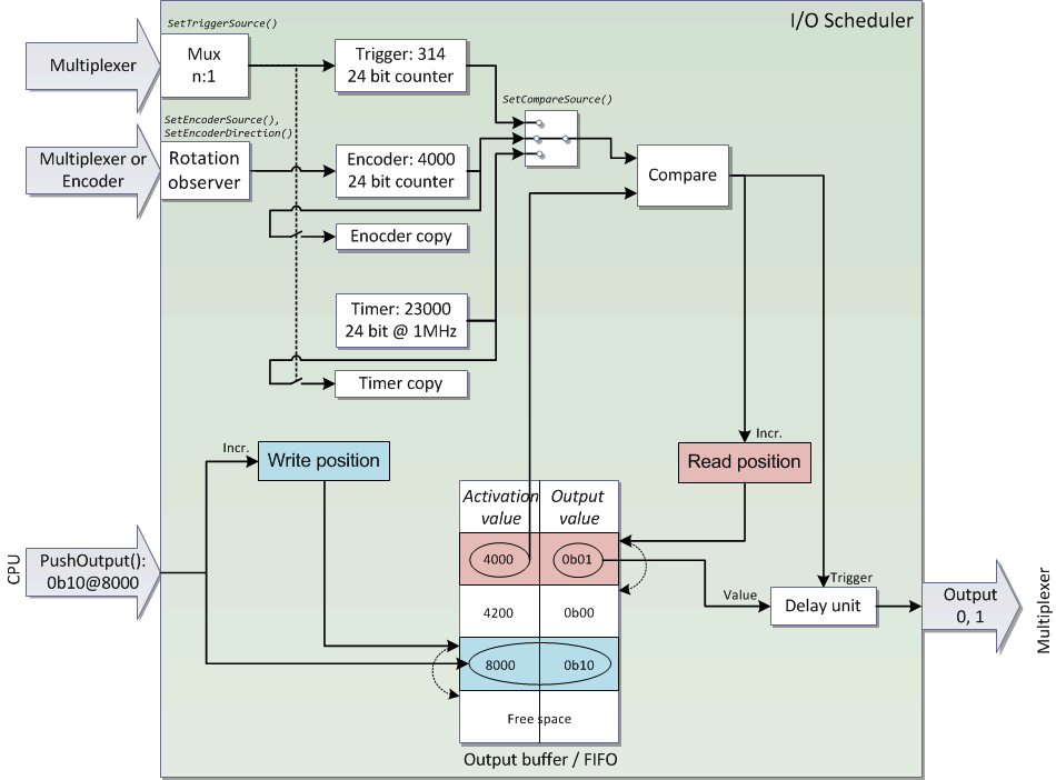
The following image shows the internal structure of the I/O Scheduler, configured for encoder mode and some example values:
The size of the output buffer depends on the FPGA firmware (see Hardware, library and firmware dependencies) and can be read with GetBufferMaxElementCount(). The currently used space can be obtained by calling GetBufferFillLevel().
All counter values are 24 bit wide. The unit always compares the oldest valid buffer entry with the selected counter. When both values are equal, the output value of the entry is used for setting the output signal and the entry is removed from the buffer, moving to the next entry.
An additional delay unit can be used to create an output signal with a specified delay and hold time (see SetOutputPulsTiming()).
Current I/O Scheduler implementations have two output signals. Therefore, two bits are used for the output value in in each buffer entry.
In Encoder and Timer mode, software often needs to calculate the next activation value after a trigger event occurred. In order to reduce real-time requirements for software, copy registers exist for both counters. They can be used by software to get the exact counter value during the last trigger event and calculate the activation value just by adding a fixed offset. The offset is equal to the desired time or position difference since the trigger event occurred.
New versions of the I/O scheduler provide additional features:
The I/O Scheduler can be in two states: stopped or active.
Certain functions can only be called during initialization while the I/O Scheduler is stopped. Other functions can only be called while the I/O Scheduler is active. Start() is used to change the state from stopped to active. Reset() is used to reset everything to default values, but can also be used to stop the unit.
The following table lists the callability for all functions depending on the state:
| Function | I/O Scheduler state | |
|---|---|---|
| Stopped | Active | |
| SetAutomaticRequeueMode() | yes | no |
| SetCompareSource() | yes | no |
| SetTriggerSource() | yes | no |
| SetEncoderSource() | yes | no |
| SetEncoderDirection() | yes | no |
| SetOutputPulsTiming() | yes | no |
| Start() | yes | no |
| Reset() | yes | yes |
| SetCounterResetSource() | yes | yes |
| SetCounterFreeze() | yes | yes |
| GetBufferMaxElementCount() | yes | yes |
| GetNumberOfOutputs() | yes | yes |
| PushValue() | no | yes |
| GetCounter() | no | yes |
| GetBufferFillLevel() | no | yes |
The following code example demonstrates the use of the I/O Scheduler:
// Connection of the FPGA units:
//
// triggerUnit(0) -> multiplexer(0) +----------------------------------------> digitalOut(0)
// |
// +-> ioScheduler[0](0) -> multiplexer(1) -> digitalOut(1)
// |
// +-> ioScheduler[0](1) -> multiplexer(2) -> digitalOut(2)
// |
// +-> ioScheduler[1](0) -> multiplexer(3) -> digitalOut(3)
VIB::Multiplexer multiplexer;
VIB::IOScheduler ioScheduler[2];
VIB::DigitalOutput digitalOut;
VIB::TriggerGenerator triggerUnit;
// Open devices:
// Multiplexer:
multiplexer.Open();
// both I/O Schedulers:
ioScheduler[0].Open(0);
ioScheduler[0].Open(1);
// Digital Output:
digitalOut.Open(0);
// Trigger Unit:
triggerUnit.Open();
// Trigger Unit configuration:
// use Generator with 100 Hz signal:
triggerUnit.ConfigureSet("GenA_tLow=5ms GenA_tHigh=5ms");
// connect signal to output 0 of the unit:
triggerUnit.ConfigureSet("TrigOut0_Mux=GenA");
// Multiplexer:
// make sure that the 100 Hz signal is disconnected from the I/O schedulers, will be reconnected later:
multiplexer.ConnectOutput(0, VIB::Multiplexer::MUX_SRC_OFF);
// Connect I/O Scheduler output signals to Multiplexer output 1...3:
multiplexer.ConnectOutput(1, VIB::Multiplexer::MUX_SRC_IOSCHEDULER_0_OUT0);
multiplexer.ConnectOutput(2, VIB::Multiplexer::MUX_SRC_IOSCHEDULER_0_OUT1);
multiplexer.ConnectOutput(3, VIB::Multiplexer::MUX_SRC_IOSCHEDULER_1_OUT0);
// Digital Outputs:
// use Multiplexer outputs as source:
// I/O Schedulers:
// Reset I/O Schedulers:
ioScheduler[0].Reset();
ioScheduler[1].Reset();
// Select multiplexer line 0 as trigger source
ioScheduler[0].SetTriggerSource(0, false);
ioScheduler[1].SetTriggerSource(0, false);
// Set delay and on time for the second I/O scheduler (8 ms delay, 2 ms active):
ioScheduler[1].SetOutputPulsTiming(8*1000, 2*1000);
// start the I/O Schedulers:
ioScheduler[0].Start();
ioScheduler[1].Start();
// Push five values into each I/O Scheduler
const unsigned int StartDelay = 3 + 1; // the first trigger starts with value 1
const unsigned int StepMul = 2;
for (int i = 0; i < 5; i++)
{
// first I/O Scheduler: we want to toggle both outputs (bits) at the same time => value 1 or 2
ioScheduler[0].PushValue(StartDelay+StepMul*i, i % 2 == 0 ? 1 : 2);
// second I/O Scheduler: uses specified pulse timing, we only need a value of 1
ioScheduler[1].PushValue(StartDelay+StepMul*i, 1);
}
// finally, connect the 100 Hz signal to the I/O Scheduler
multiplexer.ConnectOutput(0, VIB::Multiplexer::MUX_SRC_TRIGGEN_OUT0);
// wait until all elements are sent
unsigned int iFillLevel = 0;
do
{
// read only the buffer level of the first I/O Scheduler, the second unit should have the same level:
ioScheduler[0].GetBufferFillLevel(iFillLevel);
} while (iFillLevel > 0);
// disconnect the 100 Hz signal from the schedulers
multiplexer.ConnectOutput(0, VIB::Multiplexer::MUX_SRC_OFF);
This class controls a group of digital output signals. Definition VIB_Interface.h:474 @ DIG_OUT_SRC_MUX_OUT1 Multiplexer Output 1. Definition VIB_Interface.h:482 @ DIG_OUT_SRC_MUX_OUT0 Multiplexer Output 0. Definition VIB_Interface.h:481 @ DIG_OUT_SRC_MUX_OUT3 Multiplexer Output 3. Definition VIB_Interface.h:484 @ DIG_OUT_SRC_MUX_OUT2 Multiplexer Output 2. Definition VIB_Interface.h:483 bool SetSource(unsigned int BitIndex, OUT_SOURCE Source, bool InvertOutput) Sets the source for the specified output signal. Definition DigitalOutput.cpp:154 This class controls the I/O Scheduler which can store and emit output signals in hard real-time. Definition VIB_Interface.h:837 bool SetTriggerSource(const unsigned int InputIndex, const bool InvertInput) Selects the Multiplexer output signal to be used as trigger event. Definition IOScheduler.cpp:598 bool PushValue(const unsigned int CompareValue, const unsigned int OutputValue) Pushes a new entry into the circular buffer within the FPGA. Definition IOScheduler.cpp:710 bool Start() Starts the I/O Scheduler logic within the FPGA. Definition IOScheduler.cpp:524 bool SetOutputPulsTiming(const unsigned int Delay_us, const unsigned int OnTime_us) Configures the output delay and hold time. Definition IOScheduler.cpp:667 bool GetBufferFillLevel(unsigned int &BufferFillLevel) Returns the number of valid entries in the circular buffer. Definition IOScheduler.cpp:735 This class controls the RTCC Multiplexer which connects signal sources and sinks with each other. Definition VIB_Interface.h:746 @ MUX_SRC_TRIGGEN_OUT0 TriggerGenerator output 0. Definition VIB_Interface.h:775 @ MUX_SRC_IOSCHEDULER_0_OUT1 IOScheduler unit 0, output 1. Definition VIB_Interface.h:780 @ MUX_SRC_IOSCHEDULER_1_OUT0 IOScheduler unit 1, output 0. Definition VIB_Interface.h:781 @ MUX_SRC_IOSCHEDULER_0_OUT0 IOScheduler unit 0, output 0. Definition VIB_Interface.h:779 bool ConnectOutput(unsigned int OutputIndex, Multiplexer::MUX_SOURCE Source) Selects the source signal for the specified output line. Definition Multiplexer.cpp:474 bool ConfigureSet(const char Command[]) Generic function for controlling the FPGA trigger unit. Definition TriggerGenerator.cpp:619 Please note that error checking was removed to keep the code as simple as possible. The following image shows the signals that can be measured at the digital output terminals: 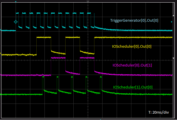 Measured input and output signals |
|
The following example demonstrates the effect of the different encoder edge modes. An encoder signal on the first RS-422 input connector with two phases and a zero pulse are required. //MainMux
multiplexer.ConnectOutput(0, VIB::Multiplexer::MUX_SRC_SYNC_2);
multiplexer.ConnectOutput(1, VIB::Multiplexer::MUX_SRC_IOSCHEDULER_0_OUT0);
multiplexer.ConnectOutput(2, VIB::Multiplexer::MUX_SRC_SYNC_0);
multiplexer.ConnectOutput(3, VIB::Multiplexer::MUX_SRC_SYNC_1);
//MuxLines to DigOut
for (UINT32 iMux=0; iMux<4; iMux++)
digitalOut.SetSource(iMux, (VIB::DigitalOutput::OUT_SOURCE)(VIB::DigitalOutput::DIG_OUT_SRC_MUX_OUT0+iMux), false);
const VIB::IOScheduler::IO_SCHEDULER_ENC_EDGE_MODE TestEdgeMode[] = {
// Test all four encoder edge modes
for (UINT32 iTest=0; iTest<4; iTest++)
{
//IOScheduler (re)config
ioScheduler.Reset();
ioScheduler.SetCounterFreeze(true);
ioScheduler.SetAutomaticRequeueMode(true);
ioScheduler.SetEncoderSource(VIB::IOScheduler::IO_SCHEDULER_ENC_SRC_SYNC_0_0, TestEdgeMode[iTest]);
ioScheduler.SetOutputPulsTiming(0, 1*1000);
ioScheduler.Start();
ioScheduler.PushValue(1, 0x1);
ioScheduler.PushValue(2, 0x1);
ioScheduler.PushValue(3, 0x1);
ioScheduler.PushValue(4, 0x1);
ioScheduler.SetCounterFreeze(false);
HMI_WaitForKey();
}
OUT_SOURCE Sources for the digital outputs, used with SetSource(). Definition VIB_Interface.h:479 bool SetAutomaticRequeueMode(const bool boAutoRequeue) If automatic requeue mode is enabled, used output values will be added to the circular buffer again. Definition IOScheduler.cpp:693 bool SetEncoderSource(const IOScheduler::IO_SCHEDULER_ENC_SRC encSrc, const IOScheduler::IO_SCHEDULER_ENC_EDGE_MODE encMode) Selects the source signal for encoder mode. Definition IOScheduler.cpp:617 bool SetCounterResetSource(const IOScheduler::IO_SCHEDULER_RST_SRC rstSrc, const bool InvertInput, const bool EdgeSensitive) Selects and configures the signal to reset the counters. Definition IOScheduler.cpp:648 bool SetCounterFreeze(const bool boFreezed) Freezes the counters and counter copy registers. Definition IOScheduler.cpp:570 bool SetCompareSource(const IOScheduler::IO_SCHEDULER_CMP_SRC cmpSrc) Selects the counter which is compared against the current trigger value. Definition IOScheduler.cpp:583 @ IO_SCHEDULER_RST_SRC_MUX_OUT0 Multiplexer Output 0. Definition VIB_Interface.h:910 @ IO_SCHEDULER_ENC_SRC_SYNC_0_0 SYNC Unit 0 Input 0. Definition VIB_Interface.h:858 IO_SCHEDULER_ENC_EDGE_MODE Encoder edge detection mode, used by SetEncoderSource(). Definition VIB_Interface.h:890 @ IO_SCHEDULER_ENC_EDGE_MODE_AB_BOTH Counter increments on both edges for both encoder signals. Definition VIB_Interface.h:894 @ IO_SCHEDULER_ENC_EDGE_MODE_A_RISING Counter increments on the rising edge of the first signal. Definition VIB_Interface.h:891 @ IO_SCHEDULER_ENC_EDGE_MODE_A_BOTH Counter increments on rising and falling edge of the first signal. Definition VIB_Interface.h:893 @ IO_SCHEDULER_ENC_EDGE_MODE_A_FALLING Counter increments on the falling edge of the first signal. Definition VIB_Interface.h:892 @ IO_SCHEDULER_CMP_SRC_ENCODER Encoder mode, can be configured with SetEncoderSource() and SetEncoderDirection(). Definition VIB_Interface.h:851 @ MUX_SRC_SYNC_1 SYNC group 0, signal 1. Definition VIB_Interface.h:772 @ MUX_SRC_SYNC_0 SYNC group 0, signal 0. Definition VIB_Interface.h:771 @ MUX_SRC_SYNC_2 SYNC group 0, signal 2. Definition VIB_Interface.h:773 The following image shows the measured signals: 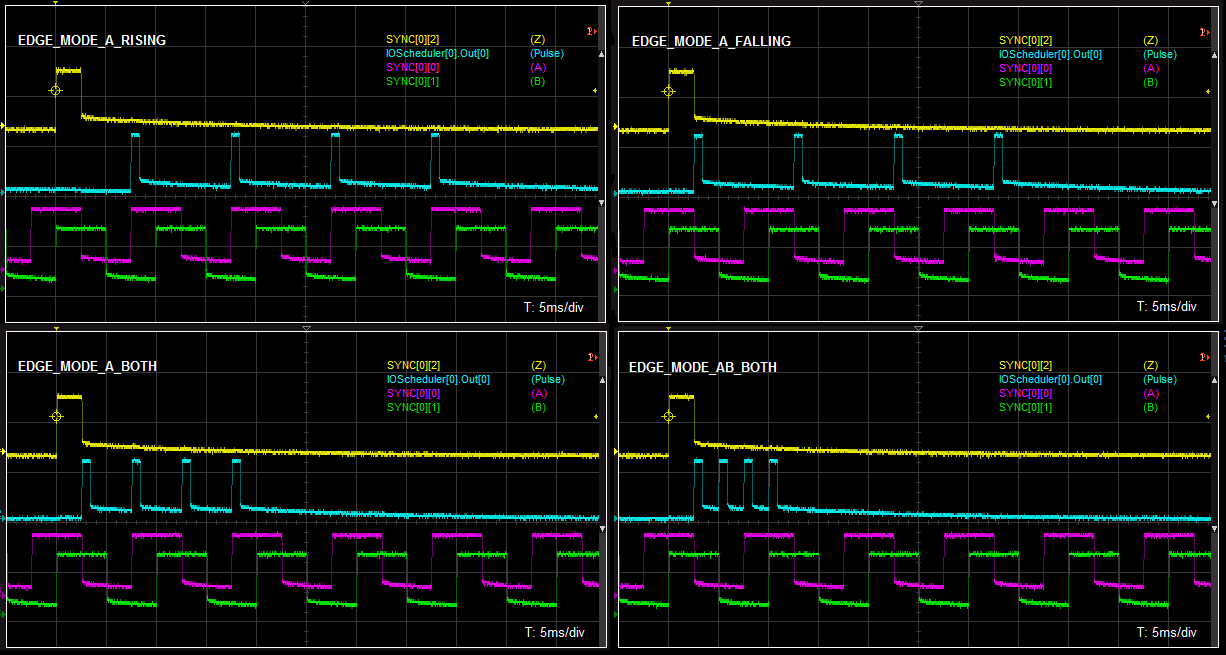 Measured input and output signals |
| Hardware | Library Version | FPGA Version | Features | |||||||
|---|---|---|---|---|---|---|---|---|---|---|
| I/O Scheduler units | Buffer size | Advanced Features | ||||||||
| VisionBox AGE-X5 / AGE-X6 | 1.6.5.6 | 1.0.0.42 | 8 | 1024 | yes | |||||
| VisionBox AGE-X4 / Machine Vision Controller | 1.6.5.3 | 1.0.0.39 | 8 | 1024 | yes | |||||
| 1.6.3 | 1.0.0.28 | 4 | 128 | no | ||||||
| VisionBox AGE-X3 | 1.6.2 | 1.0.0.25 | 2 | 128 | no | |||||
| VisionBox AGE-X2 | 1.6.5.3 | 1.0.0.38 | 4 | 1024 | yes | |||||
| 1.5.2 | 1.0.0.23 | 128 | no | |||||||
| 1.5.1 | 1.0.0.21 | 16 | ||||||||
| 1.5.0 | 1.0.0.20 | |||||||||
| VisionBox AI | 1.7.8.0 | 1.0.0.73 | 4 | 1024 | no | |||||
| VisionBox DAYTONA | 1.6.8.3 | 1.0.0.46 | 1 | 256 | yes | |||||
| VisionBox LE MANS | 1.6.5 | 1.0.0.31 | 4 | 128 | no | |||||
| VisionCam XM2 | 1.7.9.0 | 1.0.0.78 | 4 | 1024 | yes | |||||
| 1.0.0.74 | 2 | |||||||||
| VisionCam XM | 1.6.5.3 | 1.0.0.43 | 2 | 128 | yes | |||||
| 1.6.4 | 1.0.0.30 | no | ||||||||
| VisionSensor PV3 + I/O Expansion | 1.7.10.0 | 1.0.0.75 | 4 | 1024 | yes | |||||
| Machine Vision Manager | 1.6.5.4 | 1.0.0.69 | 4 | 1024 | yes | |||||
| 1.6.3 | 1.0.0.27 | 128 | no | |||||||
Public Types | |
| enum | IO_SCHEDULER_CMP_SRC |
| Operation mode type definition. More... | |
| enum | IO_SCHEDULER_COUNTER |
| Available counters, used by GetCounter(). More... | |
| enum | IO_SCHEDULER_ENC_EDGE_MODE |
| Encoder edge detection mode, used by SetEncoderSource(). More... | |
| enum | IO_SCHEDULER_ENC_SRC |
| The trigger source type definition for the Encoder counter, used by SetEncoderSource(). More... | |
| enum | IO_SCHEDULER_ENCODER_DIR |
| Encoder Direction, used by SetEncoderDirection(). More... | |
| enum | IO_SCHEDULER_RST_SRC |
| The sources which reset the counter, used by SetCounterResetSource(). More... | |
Public Member Functions | |
| bool | GetBufferFillLevel (unsigned int &BufferFillLevel) |
| Returns the number of valid entries in the circular buffer. | |
| bool | GetBufferMaxElementCount (unsigned int &BufferSize) |
| Returns the maximum space for elements inside the circular buffer. | |
| bool | GetCounter (const IOScheduler::IO_SCHEDULER_COUNTER CounterType, unsigned int &CounterValue) |
| Read a counter value from the FPGA. | |
| bool | GetNumberOfOutputs (unsigned int &NumberOfOutputs) |
| Returns the number output lines of this unit. | |
| IOScheduler () | |
| Default constructor for the device object. | |
| bool | PushValue (const unsigned int CompareValue, const unsigned int OutputValue) |
| Pushes a new entry into the circular buffer within the FPGA. | |
| bool | Reset () |
| Resets the I/O Scheduler logic. | |
| bool | SetAutomaticRequeueMode (const bool boAutoRequeue) |
| If automatic requeue mode is enabled, used output values will be added to the circular buffer again. | |
| bool | SetCompareSource (const IOScheduler::IO_SCHEDULER_CMP_SRC cmpSrc) |
| Selects the counter which is compared against the current trigger value. | |
| bool | SetCounterFreeze (const bool boFreezed) |
| Freezes the counters and counter copy registers. | |
| bool | SetCounterResetSource (const IOScheduler::IO_SCHEDULER_RST_SRC rstSrc, const bool InvertInput, const bool EdgeSensitive) |
| Selects and configures the signal to reset the counters. | |
| bool | SetEncoderDirection (const IOScheduler::IO_SCHEDULER_ENCODER_DIR EncoderDir) |
| Sets the direction of the encoder signal in encoder mode. | |
| bool | SetEncoderSource (const IOScheduler::IO_SCHEDULER_ENC_SRC encSrc, const IOScheduler::IO_SCHEDULER_ENC_EDGE_MODE encMode) |
| Selects the source signal for encoder mode. | |
| bool | SetOutputPulsTiming (const unsigned int Delay_us, const unsigned int OnTime_us) |
| Configures the output delay and hold time. | |
| bool | SetTriggerSource (const unsigned int InputIndex, const bool InvertInput) |
| Selects the Multiplexer output signal to be used as trigger event. | |
| bool | Start () |
| Starts the I/O Scheduler logic within the FPGA. | |
| Public Member Functions inherited from VIB::iDevice | |
| bool | Close () |
| Closes a device. | |
| iDevice (const iDevice &device) | |
| The copy constructor makes a copy of the existing device object. | |
| bool | isOpen (bool &state) |
| Returns the open state of a device object. | |
| bool | Open (unsigned int Index=0) |
| Opens a device. | |
| iDevice & | operator= (const iDevice &device) |
| The assignment operator makes a copy of the existing device object. | |
| virtual | ~iDevice () |
| Deletes the device object. | |
Operation mode type definition.
Selects which counter is compared against the trigger activation value of the current buffer entry.
| Enumerator | ||
|---|---|---|
| IO_SCHEDULER_CMP_SRC_TRIGGER | 0x0 | Trigger mode, signal can selected via SetTriggerSource(). |
| IO_SCHEDULER_CMP_SRC_ENCODER | 0x1 | Encoder mode, can be configured with SetEncoderSource() and SetEncoderDirection(). |
| IO_SCHEDULER_CMP_SRC_TIMER | 0x2 | Timer mode. |
Available counters, used by GetCounter().
Encoder edge detection mode, used by SetEncoderSource().
| Enumerator | ||
|---|---|---|
| IO_SCHEDULER_ENC_EDGE_MODE_A_RISING | 0 | Counter increments on the rising edge of the first signal. |
| IO_SCHEDULER_ENC_EDGE_MODE_A_FALLING | Counter increments on the falling edge of the first signal. | |
| IO_SCHEDULER_ENC_EDGE_MODE_A_BOTH | Counter increments on rising and falling edge of the first signal. | |
| IO_SCHEDULER_ENC_EDGE_MODE_AB_BOTH | Counter increments on both edges for both encoder signals. | |
| IO_SCHEDULER_ENC_EDGE_MODE_AB_ENCODER | Counter increments or decrements depending on the encoder direction and the configured direction, see SetEncoderDirection(). | |
The trigger source type definition for the Encoder counter, used by SetEncoderSource().
Encoder Direction, used by SetEncoderDirection().
| Enumerator | ||
|---|---|---|
| IO_SCHEDULER_ENCODER_DIR_NORMAL | 0x0 | Normal encoder direction. |
| IO_SCHEDULER_ENCODER_DIR_REVERSE | 0x1 | Reversed encoder direction. |
The sources which reset the counter, used by SetCounterResetSource().
| VIB::IOScheduler::IOScheduler | ( | ) |
Default constructor for the device object.
The device must be opened with Open() before it can be used.
| bool VIB::IOScheduler::GetBufferFillLevel | ( | unsigned int & | BufferFillLevel | ) |
Returns the number of valid entries in the circular buffer.
| BufferFillLevel | Number of entries |
true for success, use VIBSystem::GetLastErrorString() for an error description| bool VIB::IOScheduler::GetBufferMaxElementCount | ( | unsigned int & | BufferSize | ) |
Returns the maximum space for elements inside the circular buffer.
If GetBufferFillLevel() is equal to GetBufferMaxElementCount(), no element can be added / pushed
| BufferSize | Number of entries that can be pushed with PushValue() |
true for success, use VIBSystem::GetLastErrorString() for an error description| bool VIB::IOScheduler::GetCounter | ( | const IOScheduler::IO_SCHEDULER_COUNTER | CounterType, |
| unsigned int & | CounterValue ) |
Read a counter value from the FPGA.
| CounterType | Counter type to read |
| CounterValue | Counter value of the given type |
true for success, use VIBSystem::GetLastErrorString() for an error description| bool VIB::IOScheduler::GetNumberOfOutputs | ( | unsigned int & | NumberOfOutputs | ) |
Returns the number output lines of this unit.
| NumberOfOutputs | Number of outputs |
true for success, use VIBSystem::GetLastErrorString() for an error description| bool VIB::IOScheduler::PushValue | ( | const unsigned int | CompareValue, |
| const unsigned int | OutputValue ) |
Pushes a new entry into the circular buffer within the FPGA.
| CompareValue | 24 bit activation value which is compared against the selected counter, the upper 8 bits are ignored |
| OutputValue | Binary representation of the output signal, two LSBs are currently used |
true for success, use VIBSystem::GetLastErrorString() for an error description| bool VIB::IOScheduler::Reset | ( | ) |
Resets the I/O Scheduler logic.
The unit will be stopped if it was running before.
The function sets the following default values:
true for success, use VIBSystem::GetLastErrorString() for an error description | bool VIB::IOScheduler::SetAutomaticRequeueMode | ( | const bool | active | ) |
If automatic requeue mode is enabled, used output values will be added to the circular buffer again.
After the comparison of the current trigger activation value was true, the entry will be added to the circular buffer again. This enables using recurring sequences without CPU interaction.
In order to reset the sequence, the reset source (SetCounterResetSource()) can be used. At reset, the compare counter values are set to zero and the buffer moves back to the first entry with the lowest trigger value.
PushValue(1, 0);| active | Enable automatic requeue mode |
true for success, use VIBSystem::GetLastErrorString() for an error description| bool VIB::IOScheduler::SetCompareSource | ( | const IOScheduler::IO_SCHEDULER_CMP_SRC | cmpSrc | ) |
Selects the counter which is compared against the current trigger value.
| cmpSrc | Counter to use for comparison |
true for success, use VIBSystem::GetLastErrorString() for an error description| bool VIB::IOScheduler::SetCounterFreeze | ( | const bool | active | ) |
Freezes the counters and counter copy registers.
If the freeze state is activated, the counters are stopped from counting. Any trigger or encoder event is ignored and the timer is stopped. No update of the counter copy registers will be done while the counters are frozen.
A reset event resets the counters regardless of the freeze state.
| active | Freeze state |
true for success, use VIBSystem::GetLastErrorString() for an error description| bool VIB::IOScheduler::SetCounterResetSource | ( | const IOScheduler::IO_SCHEDULER_RST_SRC | rstSrc, |
| const bool | InvertInput, | ||
| const bool | EdgeSensitive ) |
Selects and configures the signal to reset the counters.
The reset signal sets the counters back to zero, but not the copy registers. The reset will be done regardless of the freeze state.
| rstSrc | Signal or constant value which will be used |
| InvertInput | Polarity of the reset signal |
| EdgeSensitive | false: reset signal is level sensitive true: reset signal is edge sensitive |
true for success, use VIBSystem::GetLastErrorString() for an error description| bool VIB::IOScheduler::SetEncoderDirection | ( | const IOScheduler::IO_SCHEDULER_ENCODER_DIR | EncoderDir | ) |
Sets the direction of the encoder signal in encoder mode.
This function can only be used after configuring the encoder source with SetEncoderSource(..., IOScheduler::IO_SCHEDULER_ENC_EDGE_MODE_AB_ENCODER).
| EncoderDir | Encoder direction |
true for success, use VIBSystem::GetLastErrorString() for an error description| bool VIB::IOScheduler::SetEncoderSource | ( | const IOScheduler::IO_SCHEDULER_ENC_SRC | encSrc, |
| const IOScheduler::IO_SCHEDULER_ENC_EDGE_MODE | encMode ) |
Selects the source signal for encoder mode.
Depending on the edge mode, one signal (A) or two phase signals (A, B) of a rotary encoder are used to update the encoder counter.
| encSrc | Select the source for encoder signal A, signal B will be (encSrc+1) |
| encMode | Specifies the edge mode, when and how to update the counter |
true for success, use VIBSystem::GetLastErrorString() for an error description | bool VIB::IOScheduler::SetOutputPulsTiming | ( | const unsigned int | Delay_us, |
| const unsigned int | OnTime_us ) |
Configures the output delay and hold time.
A delay can be specified after which the output value of the buffer entry gets transferred to the output of the I/O Scheduler.
A non-zero hold time will automatically set the output to low after the specified time. If the hold time is zero (default), the outputs have to be set explicitly to low by pushing a 0 bit with the desired location into the buffer.
| Delay_us | Delay for activating the outputs in microseconds (0...1 s), default: 0 |
| OnTime_us | Hold time for the output signal in microseconds (0...1 s), 0 for infinite, default: 0 |
true for success, use VIBSystem::GetLastErrorString() for an error description| bool VIB::IOScheduler::SetTriggerSource | ( | const unsigned int | InputIndex, |
| const bool | InvertInput ) |
Selects the Multiplexer output signal to be used as trigger event.
The signal is used for the trigger counter in triggered mode, but it can also be used in encoder and timer mode in order trigger a copy of the counter values.
| InputIndex | Index of the Multiplexer output |
| InvertInput | Signal polarity |
true for success, use VIBSystem::GetLastErrorString() for an error description| bool VIB::IOScheduler::Start | ( | ) |
Starts the I/O Scheduler logic within the FPGA.
true for success, use VIBSystem::GetLastErrorString() for an error description