|
VisionBox Interface Library
1.7.15.0 (2026-04-13)
|
|
|
VisionBox Interface Library
1.7.15.0 (2026-04-13)
|
|
This class controls the FPGA Trigger Unit.
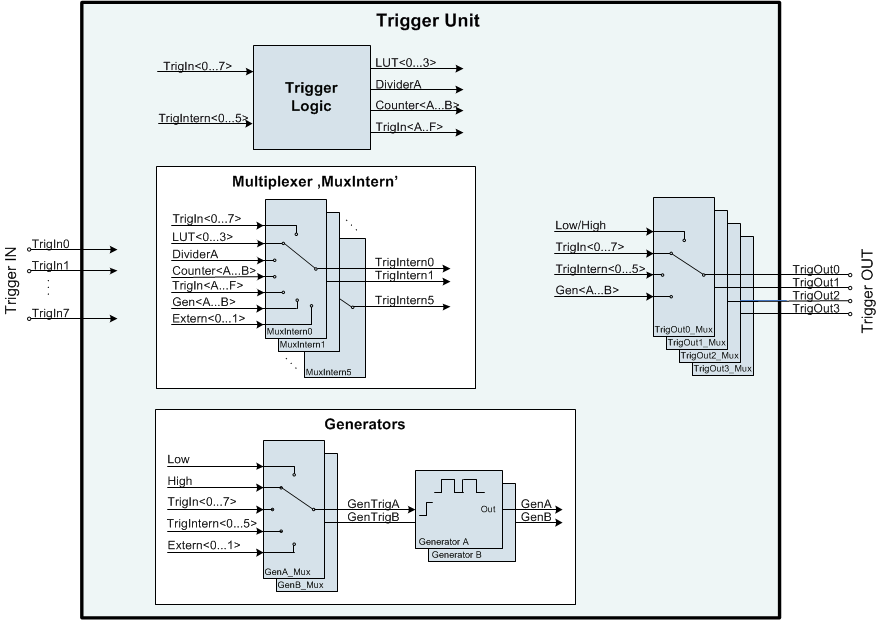
The FPGA Trigger Unit can be programmed to generate signals on different outputs. These signals can be derived from several inputs or generated internally by Signal Generators.
The Trigger Unit consists of the following components:
The API for the Trigger Unit uses two generic functions for configuration and reading of parameters: ConfigureSet() and ConfigureGet(). Both functions use a string as command.
|
The following example configures a signal generator and connects the signal to the first digital output: VIB::Multiplexer multiplexer;
VIB::TriggerGenerator triggerUnit;
VIB::DigitalOutput digitalOut;
// Open devices:
// Multiplexer:
multiplexer.Open();
// Trigger Unit:
triggerUnit.Open();
// Digital Output:
digitalOut.Open(0);
// Configure Generator to create a 1 kHz signal:
triggerUnit.ConfigureSet("GenA_tLow=500us GenA_tHigh=500us");
// Connect the signal to the output:
triggerUnit.ConfigureSet("TrigOut0_Mux=GenA");
// Connect Multilexer line to the output signal of the trigger unit:
multiplexer.ConnectOutput(0, VIB::Multiplexer::MUX_SRC_TRIGGEN_OUT0);
// Configure multiplexer line 0as source for the digital output 0:
This class controls a group of digital output signals. Definition VIB_Interface.h:474 @ DIG_OUT_SRC_MUX_OUT0 Multiplexer Output 0. Definition VIB_Interface.h:481 bool SetSource(unsigned int BitIndex, OUT_SOURCE Source, bool InvertOutput) Sets the source for the specified output signal. Definition DigitalOutput.cpp:154 This class controls the RTCC Multiplexer which connects signal sources and sinks with each other. Definition VIB_Interface.h:746 @ MUX_SRC_TRIGGEN_OUT0 TriggerGenerator output 0. Definition VIB_Interface.h:775 bool ConnectOutput(unsigned int OutputIndex, Multiplexer::MUX_SOURCE Source) Selects the source signal for the specified output line. Definition Multiplexer.cpp:474 bool ConfigureSet(const char Command[]) Generic function for controlling the FPGA trigger unit. Definition TriggerGenerator.cpp:619 Please note that error checking was removed to keep the code as simple as possible. |
The following table shows the mapping of input and output ports for the Trigger Unit depending on the hardware:
| Hardware | Trigger input | Trigger output | ||
|---|---|---|---|---|
| Name | Description | Name | Description | |
| VisionBox AGE-X2/3/4/5 | TrigIn<0...7> | Multiplexer output signals 0...N | TrigOut<0...3> | Available as source for the Multiplexer unit: Multiplexer::MUX_SOURCE |
| Machine Vision Controller | ||||
| VisionBox LE MANS | ||||
| VisionBox AI | ||||
| VisionCam XM/XM2 | ||||
| VisionSensor PV3 + I/O Expansion | ||||
| Machine Vision Manager 1/2 | ||||
| VisionBox DAYTONA | TrigIn<0...3> | |||
| VisionBox AGE-X1 | TrigIn<0...2> | RS-422 Input 0...2 | Available as source signals for the Strobe and CameraTrigger units: Strobe::STROBE_SOURCE, CameraTrigger::TRG_SOURCE | |
TrigIn<3...5> | Digital Input 0...2 | |||
TrigIn<6...7> | Trigger Output of Strobe Unit 0 and 1 | |||
The following table lists the signals which can be used with the corresponding multiplexers:
| Input Signal | Multiplexer | ||||
|---|---|---|---|---|---|
| Signal Name | Description | TrigOut<0...3>_Mux | Gen<A...B>_Mux | MuxIntern<0...7> | |
Low | Logic '0' | Yes | Yes | No | |
High | Logic '1' | Yes | Yes | No | |
TrigIn<0...7> | Trigger Input signal | Yes | Yes | Yes | |
LUT<0...3> | Trigger Logic output signal | No | No | Yes | |
TrigIntern<0...7> | Internal Multiplexer output signal | Yes | Yes | No | |
Gen<A...B> | Generator output signal | Yes | No | Yes | |
Extern<0...1> | Externally supplied trigger signal (e.g. from different FPGA) | No | GenA: Extern0 GenB: Extern1 | Yes | |
The output signal of each multiplexer can be inverted independently.
Controls the output signals of the Trigger Unit.
This multiplexer controls the trigger signal for each signal generator in when used triggered mode.
This multiplexer is used to connect the different internal units with each other. The output signals of this multiplexer are available as TrigIntern<0...7>. The actual number of multiplexers depends on the firmware version, see Hardware and firmware dependencies.
The Signal Generators can be used to generate a square-wave signal or to produce an externally triggered pulse with a user defined length and delay. The behavior of each signal generator is controlled by the following parameters:
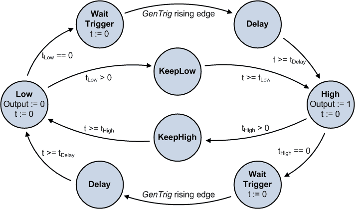
The parameters tLow and tHigh determine how long the state machine will remain in the Low and High state. If both values are set to a non-zero value, the state machine will continuously toggle between Low and High.
If one of both values is set to zero, the generator is in triggered mode. It will remain in the state with the zero value until it gets triggered by the rising edge of GenTrig<A|B>. Before switching to the opposite state, the state machine will first go to the Delay state and wait for tDelay to expire.
The Trigger Logic is used to generate additional signals which are derived from the trigger inputs or from other derived signals (TrigIntern).
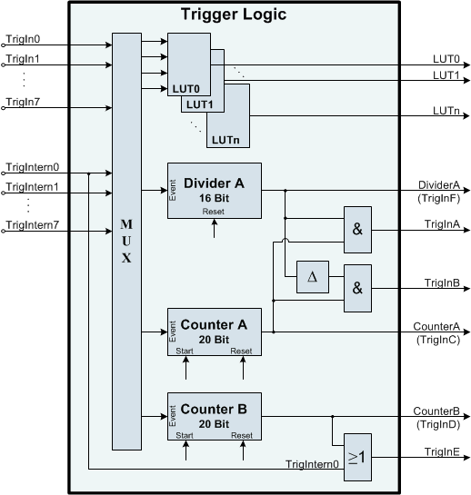
The trigger logic consists of Lookup Tables, Dividers and Counters. The actual number of units depends on the type of hardware and the firmware version, see Hardware and firmware dependencies.
The Lookup Tables can be used to make logical operations between signals. Up to four input signals are simultaneously available for evaluation. Each lookup table is configured by using an equation.
Input signals: TrigIn<0...7>, TrigIntern<0...7>
Operators: & (and), | (or), ! (not)
There is no operator precedence between & and |. Evaluation takes place from left to right. Parenthesis can be used to change the priority.
Example:
The Divider is used to reduce the frequency of the input signal, e.g. to generate a line trigger based on the signal of a connected encoder. For each event, the output signal DividerA / TrigInF will toggle between 0 and 1.
The output signals TrigInA and TrigInB are masked by the output of CounterA. TrigInB only shows a very short pulse for each change in the divider output. This pulse can then be used as trigger for the Generator unit for example.
The following table lists all parameters:
| Parameter | Description |
|---|---|
| DividerA | Divider value and Input events |
| DividerA_Reset | Reset modeOff: Divider output is activeOn: Divider is held in reset and output is lowTrigIntern<2...3>: Divider is reset by rising edge of selected signal |
Example:
If one of the directional encoder event modes is selected (TrigIn0/1_Encoder_[CW|CCW]), the Divider will hold the last output signal while running in reverse direction. Additionally, the number of events in reverse direction will be counted (up to 65536) in order to enable the output signal at the same encoder position again, where the direction first was reversed. A reset signal at TrigIntern<2...3> will be ignored while the encoder position is negative.
The Counters are used to generate an output signal after a user defined number of input events.
The ON and OFF value are used to adjust the counter position at which the output gets set to 1 and 0.
The following table lists all parameters:
| Parameter | Description |
|---|---|
| Counter<A...B> | Maximum counter value and Input events |
| Counter<A...B>_ON | ON counter value (set output to high) (default: Counter<A...B>_ON = Counter<A...B>) |
| Counter<A...B>_OFF | OFF counter value (set output to low) (default: Counter<A...B>_OFF = 0) |
| Counter<A...B>_Start | Start condition, evaluated when counter value is 0Off: counter not activeOn: start countingTrigIntern<2...3>: wait for rising edge of selected trigger signal |
| Counter<A...B>_Reset | Reset modeOff: stop counting at maximum valueAuto: automatically reset counter to 0 after reaching the maximum valueTrigIntern<2...3>: Counter is reset by rising edge of selected signal |
At counter value 0, the counter will first wait for the start condition to come true. After activation, it is incremented for every input event until the maximum counter value is reached.
The reset mode determines when the counter gets reset to 0. When using TrigIntern<2...3> as reset mode, the counter can be reset to 0 before reaching the maximum value.
If one of the directional encoder event modes is selected (TrigIn0/1_Encoder_[CW|CCW]), the counter will decrement in reverse direction.
Start/Reset parameters will reset the counter to 0. ON and OFF parameters are equal, ON has precedence. Dividers and Counters can use the following input events:
| Event value | Description |
|---|---|
<Input>_Rising | Rising edge on <Input> |
<Input>_Falling | Rising edge on <Input> |
<Input>_Both | Rising and falling edge on <Input> |
TrigIn0/1_Both | Both edges on TrigIn0 and TrigIn1 (encoder with highest frequency) |
TrigIn0/1_Encoder_CW | Encoder mode using both edges on TrigIn0 and TrigIn1 in clock-wise direction (TrigIn0 leads in phase) |
TrigIn0/1_Encoder_CCW | Encoder mode using both edges on TrigIn0 and TrigIn1 in counter-clock-wise direction (TrigIn1 leads in phase) |
Valid values for <Input> are:
TrigIn<0...7> TrigIntern<0...7> | Hardware | Supported features | ||||
|---|---|---|---|---|---|
| Generators | MuxIntern signals | Dividers | Counters | LUTs | |
| VisionBox AGE-X5 / AGE-X6 | 2 | 6 | 1 | 2 | 4 |
| VisionBox AGE-X4 / Machine Vision Controller | 2 | 6 | 1 | 2 | 4 |
| 2 | 6 | 1 | 2 | 4 | |
| VisionBox AGE-X3 | 2 | 6 | 1 | 2 | 4 |
| VisionBox AGE-X2 | 2 | 6 | 1 | 2 | 4 |
| 2 | 6 | 1 | 2 | 4 | |
| VisionBox AGE-X1 | 2 | 6 | 1 | 2 | 2 |
| 2 | 4 | 1 | 2 | - | |
| VisionBox DAYTONA | 1 | 4 | 1 | 2 | 1 |
| VisionBox LE MANS | 2 | 6 | 1 | 2 | 4 |
| VisionCam XM | 2 | 6 | 1 | 2 | 4 |
| Machine Vision Manager | 2 | 6 | 1 | 2 | 4 |
| Machine Vision Manager 2 | 2 | 4 | 1 | 2 | 2 |
Public Member Functions | |
| bool | ConfigureGet (const char Command[], unsigned int &RegisterValue) |
| Generic function to read data from the FPGA trigger unit. | |
| bool | ConfigureSet (const char Command[]) |
| Generic function for controlling the FPGA trigger unit. | |
| bool | Reset () |
| Resets the device to default settings. | |
| TriggerGenerator () | |
| Default constructor for the device object. | |
| Public Member Functions inherited from VIB::iDevice | |
| bool | Close () |
| Closes a device. | |
| iDevice (const iDevice &device) | |
| The copy constructor makes a copy of the existing device object. | |
| bool | isOpen (bool &state) |
| Returns the open state of a device object. | |
| bool | Open (unsigned int Index=0) |
| Opens a device. | |
| iDevice & | operator= (const iDevice &device) |
| The assignment operator makes a copy of the existing device object. | |
| virtual | ~iDevice () |
| Deletes the device object. | |
| VIB::TriggerGenerator::TriggerGenerator | ( | ) |
Default constructor for the device object.
The device must be opened with Open() before it can be used.
| bool VIB::TriggerGenerator::ConfigureGet | ( | const char | Command[], |
| unsigned int & | RegisterValue ) |
Generic function to read data from the FPGA trigger unit.
The command string is case insensitive. The syntax is described in the following table:
| Name | Result |
|---|---|
Version | Trigger unit firmware version number |
TrigIn | Binary representation of the Trigger Input signals |
TrigIntern | Binary representation of the internal trigger signals |
Counter<A...B>[,Reset] | Current counter value with optional counter reset |
| Command | Command string |
| RegisterValue | Reference to result data |
true for success, use VIBSystem::GetLastErrorString() for an error description | bool VIB::TriggerGenerator::ConfigureSet | ( | const char | Command[] | ) |
Generic function for controlling the FPGA trigger unit.
Each command string starts with the name of the parameter followed by a '=' character and the new value. The string is case insensitive.
Valid combinations of parameters and values are described in the following table:
| Unit | Name | Value | Example |
|---|---|---|---|
| Multiplexers | TrigOut<0...3>_Mux | <Input signal>[,invert] | "MuxIntern0=GenA,invert" |
MuxIntern<0...3> | |||
Gen<A...B>_Mux | |||
| Signal Generator | Gen<A...B>_tLow | <Low time>[ms|ns|us(default)](set to 0 for external trigger) | "GenA_tLow=0" |
Gen<A...B>_tHigh | <High time>[ms|ns|us(default)](set to 0 for external trigger) | "GenA_tHigh=50us" | |
Gen<A...B>_tDelay | <Delay time>[ms|ns|us(default)](only used in triggered mode) | "GenA_tDelay=2ms" | |
| Trigger Logic | LUT<0...3> | <LUT equation> | "LUT0=TrigIn1&TrigIntern0" |
DividerA | <Divider value>[,<Input events>] (default: TrigIn0_Rising) | "DividerA=5,TrigIn2_Falling" | |
DividerA_Reset | On|Off|TrigIntern2|TrigIntern3 | "DividerA_Reset=Off" | |
Counter<A...B> | <Max. Counter value>[,<Input events>] (default: ,TrigIn0_Rising) | "CounterB=500,TrigIn0/1_Both" | |
Counter<A...B>_ON | <Counter ON value> | "CounterB_ON=100" | |
Counter<A...B>_OFF | <Counter OFF value> | "CounterB_OFF=200" | |
Counter<A...B>_Start | Off|On|TrigIntern2|TrigIntern3 | "CounterB_Start=On" | |
Counter<A...B>_Reset | Off|Auto|TrigIntern2|TrigIntern3 | "CounterB_Reset=Auto" |
The command string can consist of multiple control commands, which are separated by spaces.
Each unit is controlled independently. For example changing TrigOut0 doesn't influence TrigOut1
| Command | Command string |
true for success, use VIBSystem::GetLastErrorString() for an error description | bool VIB::TriggerGenerator::Reset | ( | ) |
Resets the device to default settings.
All components in the trigger unit are configured to their default state.
true for success, use VIBSystem::GetLastErrorString() for an error description