|
FG Camera Library
1.7.3.0 (2026-04-13)
|
|
|
FG Camera Library
1.7.3.0 (2026-04-13)
|
|
The following AMS Dragster line scan sensors are available for the VisionCam XM:
| Sensor name | Type | eFG_CAMERA_TYPE | Number of pixels | Pixel size | Optical length |
|---|---|---|---|---|---|
| DR-2k-7 | Monochrome | FG_CAMERA_TYPE_2048_1_IMAGO_VCx_DR2K7 | 1x 2048 | 7 µm | 14.34 mm |
| DR-4k-7 | FG_CAMERA_TYPE_4096_1_IMAGO_VCx_DR4K7 | 1x 4096 | 7 µm | 28.67 mm | |
| DR-4k-3.5 | FG_CAMERA_TYPE_4096_1_IMAGO_VCx_DR4K35 | 1x 4096 | 3.5 µm | 14.34 mm | |
| DR-8k-3.5 | FG_CAMERA_TYPE_8192_1_IMAGO_VCx_DR8K35 | 1x 8192 | 3.5 µm | 28.67 mm | |
| DR-2x2k-7 | Dual Line Monochrome | FG_CAMERA_TYPE_2048_2_IMAGO_VCx_DR2X2K7 | 2x 2048 | 7 µm | 14.34 mm |
| DR-2x4k-7 | FG_CAMERA_TYPE_4096_2_IMAGO_VCx_DR2X4K7 | 2x 4096 | 7 µm | 28.67 mm | |
| DR-2x2k-7-RGB | Dual Line Color | FG_CAMERA_TYPE_2048_2_IMAGO_VCx_DR2X2K7_RGB | 2x 2048 | 7 µm | 14.34 mm |
| DR-2x4k-7-RGB | FG_CAMERA_TYPE_4096_2_IMAGO_VCx_DR2X4K7_RGB | 2x 4096 | 7 µm | 28.67 mm |
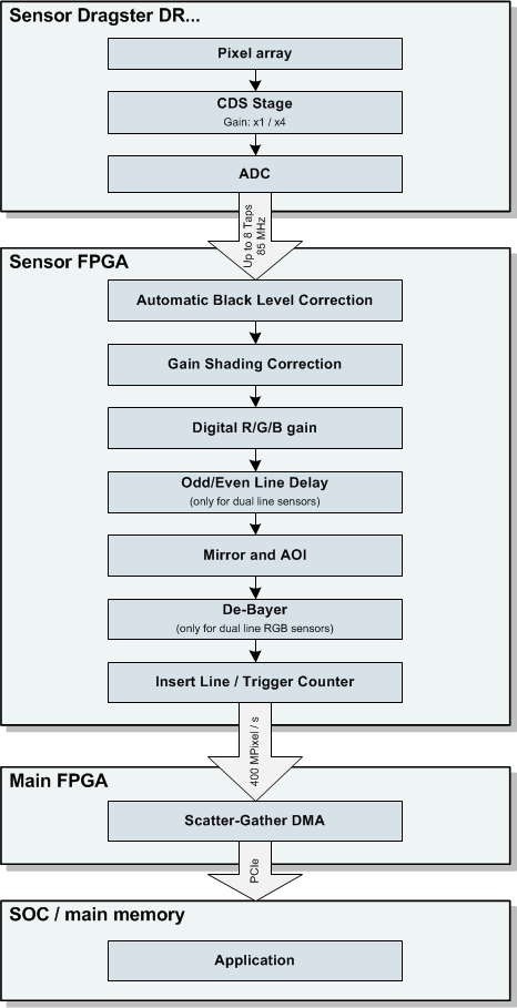
The following image shows the functional bocks and pipeline stages:
The supported pixel formats and maximum scan rates are listed below:
| Sensor type | eFG_PIXEL_TYPE | Output format | AOI width | Max. scan rate |
|---|---|---|---|---|
| Monochrome | FG_PIXEL_TYPE_Y_8 | 1 byte per pixel | ≤ 4704 | 80 kHz |
| 8192 | 46 kHz | |||
| FG_PIXEL_TYPE_Y_16 | 2 bytes per pixel containing 10 valid bits | ≤ 2352 | 80 kHz | |
| 4096 | 46 kHz | |||
| 8192 | 23 kHz | |||
| Dual Line Monochrome | FG_PIXEL_TYPE_Y_8 | Two lines with 1 byte per pixel | ≤ 2352 | 80 kHz |
| 4096 | 46 kHz | |||
| FG_PIXEL_TYPE_Y_16 | Two lines with 2 bytes per pixel containing 10 valid bits | ≤ 1176 | 80 kHz | |
| 2048 | 46 kHz | |||
| 4096 | 23 kHz | |||
| Dual Line Color | FG_PIXEL_TYPE_Y_8 | Raw mode: Two lines with 1 byte per pixel Even lines: B-G; Odd lines: G-R | ≤ 2352 | 80 kHz |
| 4096 | 46 kHz | |||
| FG_PIXEL_TYPE_Y_16 | Raw mode: Two lines with 2 bytes per pixel containing 10 valid bits Even lines: B-G; Odd lines: G-R | ≤ 1176 | 80 kHz | |
| 2048 | 46 kHz | |||
| 4096 | 23 kHz | |||
| FG_PIXEL_TYPE_RGB_24 | Demosaicing mode: One line with 3 bytes per pixel containing 8 bit R/G/B | ≤ 1560 | 80 kHz | |
| 2048 | 61 kHz | |||
| 4096 | 30 kHz | |||
| FG_PIXEL_TYPE_RGBX_32 | Demosaicing mode: One line with 4 bytes per pixel containing 8 bit R/G/B/dummy | ≤ 1176 | 80 kHz | |
| 2048 | 46 kHz | |||
| 4096 | 23 kHz |
For line scan sensors, multiple sensor lines are concatenated to complete an image.
Selecting a smaller image height reduces the latency, because all image lines have to be in memory before the buffer is given to the user. But it will also increase the processing overhead if the height is very small.
With FG_set_aoi(), the x coordinates specify the sensor columns for readout. The parameter y1 has to be zero and y2 specifies the number of lines to acquire for each image. The default image height is 512 after initialization.
Example:
The alternative function FG_set_scan_param() can also be used to specify the sensor AOI and number of scans per image (parameter image_scan_count). The parameter scan_height is normally one and image_scan_count is therefore equal to the image height. For Dual Line sensors with a pixel type of FG_PIXEL_TYPE_Y_8 or FG_PIXEL_TYPE_Y_16, the scan height can also be two. The image height is then twice the scan count value.
Example:
The following example configures an AOI width of 1024 at the sensor's center location:
The sensor supports the following special features:
| Property name | Description | FGCamera.so |
|---|---|---|
| ScanPeriod | Sensor scan period for free-run mode in microseconds (12...6553). Please note that the exposure time must be at least 2 µs shorter than the readout period. The exposure time has priority and may increase the resulting readout period. The lowest value can also be limited by the pixel format and AOI width used. | ≥ 1.1.1.0 |
| Mirror | Readout direction of the sensor. 0: normal 1: reverse | |
| CDS_Gain | Analog gain value for the CDS pixel stage. Only 1 and 4 are allowed values. | |
| InsertLineCounters | Enables or disables insertion of trigger and sensor readout counters at the beginning of each line, see also Embedded line and trigger counters: 0: disable counters (default) 1: enable counters | |
| SetGainCoeff | Sets the gain coefficients for each sensor pixel (see Shading Correction). The argument is a pointer to an array of float values containing the gain values for each pixel. The maximum gain value is 4.0. The length and arrangement of the array depends on the pixel format used. If argument is zero, the gain coefficients are reset to 1.0 for each pixel. Please note that the gain settings are lost after calling FG_install_camera() unless the SaveGainCoeff command is executed. | |
| SaveGainCoeff | Stores the current gain coefficients permanently in flash memory (see SetGainCoeff). The values are loaded automatically when calling FG_install_camera() for the next time. The argument is ignored for this option. | |
| ImageMode | Sets the image mode: 0 .. Video output 1 .. Test image mode: horizontal ramp using 10 bit | |
| LineDelay | For dual line sensors only: Selects readout delay for one of the sensor lines. This setting can be used to compensate the physical displacement of both lines depending on the transport direction used in the application. 0: no line delay (default) 1: The first line is delayed by one readout period -1: The second line is delayed by one readout period |
Additional features are described in the following sections:
The dual line sensors increase the effective line rate above the maximum scan rate of 80 kHz. Each trigger event and integration cycle will provide two scan lines within the image.
To avoid blurring in transport direction because of the increased object speed, make sure to reduce the integration time accordingly.
Depending on the transport direction, the line delay parameter can be set to 0 or +1. This will correct the line sequence in memory. Use FG_set_special_option() with the option "LineDelay".
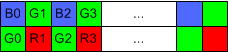
The dual line color version is similar to the monochrome version, but it uses an RGB filter with the following pixel arrangement:
When using an RGB output format with demosaicing in hardware, the following requirements must be met:
The output of the demosaicing stage is one line with three RGB components for each pixel:
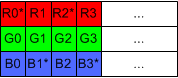
While the G component contains the full resolution, every other R- and B component is interpolated by the demosaicing filter in horizontal direction (marked with *).
It's possible to store the output with 3 bytes per pixel (FG_PIXEL_TYPE_RGB_24) or with 4 bytes per pixel (FG_PIXEL_TYPE_RGBX_32).
This format allows for higher line rates than the RGB Demosaicing format, because it doesnt contain the interpolated color components and therefore uses less PCIe and memory bandwidth.
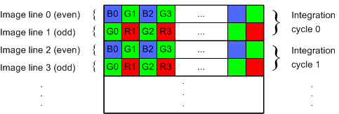
When using raw output format, each integration period results in two image lines. Even lines contain the B-G pixels and odd lines contain the G-R pixels within the returned image: The AOI y position and height must be a multiple of two when using the raw format.
With the raw Bayer format, the sensor can be triggered in TDI mode or dual line mode. The difference is in how fast the sensor gets triggered compared to the object speed and how the output lines are treated by software:
Please note:
By activating the mirror option, the sequence of the color components gets swapped within each line.
The first line in the image will always be the B-G line, regardless of line delay setting.
The processing pipeline provides independent gain values for each sensor pixel. This can be used to compensate the following problems:
The gain coefficients have to be calculated by the application. The gain values are configured using FG_set_special_option() with the option SetGainCoeff. The argument is a pointer to an array of float values containing the gain coefficients for each sensor pixel. The maximum supported gain value is 4.0 which should be enough for most situations.
The length and arrangement of the float array depends on the pixel format and AOI used:
| Sensor type | eFG_PIXEL_TYPE | Number of values | Arrangement |
|---|---|---|---|
| Single line | FG_PIXEL_TYPE_Y_8 FG_PIXEL_TYPE_Y_16 | AOI width | Gain values for each sensor pixel |
| Dual line | FG_PIXEL_TYPE_Y_8 FG_PIXEL_TYPE_Y_16 | 2x AOI width | Two lines of gain values in succession |
| FG_PIXEL_TYPE_RGB_24 FG_PIXEL_TYPE_RGBX_32 | 3x AOI width | One line of R/G/B components for each pixel |
Only gain coefficients for the configured AOI are given to the function. Gain values for sensor pixels outside of the AOI are automatically set to 1.0.
Before taking a reference image for calculation of the gain values, make sure that the following conditions are met:
 Example code for calculation and configuration of gain values
 |
The example function below takes one acquired reference image to calculate optimal the gain values for each sensor pixel. The calculation of gain values for this example is based on the average pixel values for each column within the whole image. The code can be modified to use certain regions of the image only, for example a white horzontal region between printed lines of text. The function will limit gain values to the maximum allowed value of 4.0. This is the case for regions of the image which are too dark. int ShadingCorrection( FG_IMAGE *pFgImage, // pointer to reference image for calculating the shading coefficients
bool save) // store coefficients permanently
{
eFG_PIXEL_TYPE pixelType;
unsigned int x1, x2, y1, y2;
unsigned int width, height;
unsigned int channels, pixelSize;
enum eFG_CAMERA_TYPE camera_type;
bool dualLine;
// Get AOI and pixel format
FG_get_aoi(&x1, &y1, &x2, &y2, &pixelType);
channels = pixelSize = 1;
channels = pixelSize = 3;
{
channels = 3;
pixelSize = 4;
}
else
return -1;
width = x2 - x1 + 1;
height = y2 - y1 + 1;
// Dual line sensor: we need to calculate column values for each line separately.
// We handle the two image lines as one line with twice the width:
FG_get_camera_type(&camera_type);
dualLine = (camera_type == FG_CAMERA_TYPE_2048_2_IMAGO_VCx_DR2X2K7 || camera_type == FG_CAMERA_TYPE_2048_2_IMAGO_VCx_DR2X2K7_RGB ||
camera_type == FG_CAMERA_TYPE_4096_2_IMAGO_VCx_DR2X4K7 || camera_type == FG_CAMERA_TYPE_4096_2_IMAGO_VCx_DR2X4K7_RGB);
if (dualLine && pixelType == FG_PIXEL_TYPE_Y_8)
{
width *= 2;
height /= 2;
}
std::vector<float> gainCoeff(channels * width, 1.0f); // Resulting array of gain coefficients, default: 1.0
std::vector<unsigned int> colSum(channels * width, 0); // Sum for each column
std::vector<double> colAvg(channels * width); // Average value for each column
double maxVal = 0.0; // Highest average value
// Calculate pixel sum for each column
for (unsigned int y = 0; y < height; y++)
{
for (unsigned int x = 0; x < width; x++)
{
for (unsigned int color=0; color < channels; color++)
{
unsigned int pixel;
if (pixelType == FG_PIXEL_TYPE_Y_16)
{
pixel = pSrc16[pixelSize*(x + y * width) + color];
}
else
{
pixel = pSrc8[pixelSize*(x + y * width) + color];
}
colSum[channels*x + color] += pixel;
}
}
}
// Calculate average column value and remember the highest average for all columns
for (unsigned int x = 0; x < (channels*width); x++)
{
colAvg[x] = (double)colSum[x] / (double)height;
if (colAvg[x] > maxVal)
maxVal = colAvg[x];
}
// Calculate gain coefficients for each column.
// The column with the highest average gets a gain of 1.0.
// The gain for darker columns is increased to reach the same brightness level.
for (unsigned int x = 0; x < (channels*width); x++)
{
if (colAvg[x] > 0.0)
{
float coeff = maxVal / colAvg[x];
if (coeff > 4.0f) // limit gain value
coeff = 4.0f;
gainCoeff[x] = coeff;
}
}
// Set coefficients
FG_set_special_option("SetGainCoeff", (INT64)&gainCoeff[0]);
// Save the new coefficients permanently
if (save)
FG_set_special_option("SaveGainCoeff", 0);
return 0;
}
eFG_CAMERA_TYPE The following camera models are supported by this library. Definition FG_CameraInterface.h:53 @ FG_CAMERA_TYPE_4096_2_IMAGO_VCx_DR2X4K7 IMAGO VisionCam DR2x4k7 4096x2 BW. Definition FG_CameraInterface.h:77 @ FG_CAMERA_TYPE_2048_2_IMAGO_VCx_DR2X2K7 IMAGO VisionCam DR2x2k7 2048x2 BW. Definition FG_CameraInterface.h:76 @ FG_CAMERA_TYPE_4096_2_IMAGO_VCx_DR2X4K7_RGB IMAGO VisionCam DR2x4k7 4096x2 RGB (1x GB line + 1x RG line). Definition FG_CameraInterface.h:79 @ FG_CAMERA_TYPE_2048_2_IMAGO_VCx_DR2X2K7_RGB IMAGO VisionCam DR2x2k7 2048x2 RGB (1x GB line + 1x RG line). Definition FG_CameraInterface.h:78 @ FG_PIXEL_TYPE_Y_8 1 byte per pixel, can be monochrome or raw bayer values (depending on the sensor) Definition FG_CameraInterface.h:137 @ FG_PIXEL_TYPE_Y_16 2 bytes per pixel, the number of valid bits depends on the sensor type Definition FG_CameraInterface.h:138 @ FG_PIXEL_TYPE_RGBX_32 4 bytes per pixel containing 8 bit red/green/blue/dummy. The sequence is [RGBx RGBx .... Definition FG_CameraInterface.h:139 @ FG_PIXEL_TYPE_RGB_24 3 bytes per pixel containing 8 bit red/green/blue. The sequence is [R0G0B0 R1G1B1 .... Definition FG_CameraInterface.h:140 UINT32 DLL_FG_API FG_get_camera_type(enum eFG_CAMERA_TYPE *camera_type) Returns the installed camera type. Definition FG_CameraInterface.cpp:601 This structure stores information associated with image buffers. Definition FG_CameraInterface.h:180 UINT8 *const pixel_ptr Pointer to image memory. Definition FG_CameraInterface.h:185 |
In hardware triggered mode, each trigger event results in one or two valid image lines (depending on sensor type). Multiple trigger events are required before the image is complete and returned to the user.
The RTCC can be used to adapt the the trigger signal to the desired scan rate, see Hardware trigger for examples.
After enabling the special feature InsertLineCounters, two counter values will be embedded at the beginning of each scan line (every other line for dual line sensors without demosaicing active):
The first counter can be used for detection of dropped senor lines which are caused by insufficient acquisition buffers.
The second counter is used in hardware triggered mode for detection of ignored trigger events when the trigger signal is arriving too fast. The trigger event is properly synchronized with the associated lines received from the sensor.
The storage of the counter values depends on the used pixel format, see the example code below for reading the values.
Example code for reading line and trigger counters |
int main()
{
FG_IMAGE imageList[NUM_BUFFERS];
UINT32 x1, y1, x2, y2;
UINT32 scanLines;
enum eFG_PIXEL_TYPE pixel_type;
int checkCounters = 0;
unsigned short lineCounter[2];
unsigned short trgCounter[2];
// install and configure the camera
SetupCamera();
// configure customized hardware trigger
SetupTrigger();
// get the image size for comparing the received counter values later:
FG_get_aoi(&x1, &y1, &x2, &y2, &pixel_type);
// the expected number of counter values is equal to the image height:
scanLines = y2 - y1 + 1;
// uncomment the following line when using dual line sensors without demosaicing active:
// scanLines /= 2;
// activate counters
FG_set_special_option("InsertLineCounters", 1);
// allocate image buffers
for (UINT32 i = 0; i < NUM_BUFFERS; i++)
FG_alloc_image(&imageList[i]);
// start acquisition
for (UINT32 i = 0; i < NUM_BUFFERS; i++)
FG_append_image(&imageList[i]);
// enter acquisition loop
while (isRunning)
{
FG_IMAGE currentImage;
unsigned short counterDiff;
UINT32 res = FG_get_image(¤tImage, UINT_MAX);
if (res == FG_ERROR_CODE_NoError)
{
// read the line and trigger counters for the first line in the image, depending on the pixel format:
if (pixel_type == FG_PIXEL_TYPE_RGBX_32)
{
}
{
}
else
{
}
if (checkCounters)
{
// check the received sensor lines
counterDiff = lineCounter[0] - lineCounter[1];
if (counterDiff != scanLines)
printf("%d sensor lines dropped\n", counterDiff - scanLines);
// check the trigger counter
counterDiff = trgCounter[0] - trgCounter[1];
if (counterDiff != scanLines)
printf("%d trigger events dropped\n", counterDiff - scanLines);
}
else
{
// delayed start of counter check
checkCounters = 1;
}
// store values for the next cycle
lineCounter[1] = lineCounter[0];
trgCounter[1] = trgCounter[0];
FG_append_image(¤tImage);
}
{
FG_append_image(¤tImage);
}
else // Error during waiting
return -1;
}
// abort image acquisition
// free buffers
for (UINT32 i = 0; i < NUM_BUFFERS; i++)
FG_free_image(&imageList[i]);
// Close the camera
return 0;
}
@ FG_ERROR_CODE_NoError The function was successful. Definition FG_CameraInterface.h:158 @ FG_ERROR_CODE_BrokenImage Only valid for FG_get_image(): the returned image contents are invalid. Definition FG_CameraInterface.h:163 UINT32 DLL_FG_API FG_alloc_image(FG_IMAGE *img) Allocates a new image buffer for storing sensor frames. Definition FG_CameraInterface.cpp:657 UINT32 DLL_FG_API FG_get_image(FG_IMAGE *img, UINT32 TimeOut_ms) Returns captured images to the user. Definition FG_CameraInterface.cpp:696 UINT32 DLL_FG_API FG_free_image(FG_IMAGE *img) Releases an image buffer. Definition FG_CameraInterface.cpp:670 UINT32 DLL_FG_API FG_append_image(FG_IMAGE *img) Puts an image buffer into the aquisition queue. Definition FG_CameraInterface.cpp:683 UINT32 DLL_FG_API FG_stop_image(void) Forces the camera to stop grabbing and using any buffers. Definition FG_CameraInterface.cpp:733 UINT32 DLL_FG_API FG_uninstall_camera(void) Closes the camera. Definition FG_CameraInterface.cpp:568 Please note that no error checking is performed in the examples in order to simplify the code. |