The following Lince 5M sensor models are available for the VisionCam XM2:
| Sensor | Type | eFG_CAMERA_TYPE | Number of pixels | Pixel size | Optical format |
|---|---|---|---|---|---|
| Lince5M181M | Monochrome | FG_CAMERA_TYPE_2560_2048_IMAGO_VCx_L181M | 2560 x 2048 | 5 µm x 5 µm | 1" |
| Lince5M181C | Color | FG_CAMERA_TYPE_2560_2048_IMAGO_VCx_L181C |
The supported pixel formats are listed below:
| Sensor | eFG_PIXEL_TYPE | Output format |
|---|---|---|
| Lince5M181M (Monochrome) | FG_PIXEL_TYPE_Y_8 | 1 byte per pixel |
| Lince5M181C (Color) | FG_PIXEL_TYPE_Y_8 | Raw bayer, 1 byte per pixel |
For color sensors, there is no support for demosaicing in hardware. But the function FG_set_gain_rgb() can still be used to adjust the gain for each color component within the raw bayer pixels.
The frame rate can be increased be reducing the AOI size. Use the calculator to obtain the maximum frame rate:
The sensor supports the following special features:
| Property name | Description |
|---|---|
| Mirror | Flips the image horizontally and / or vertically 0: no flipping (default) 1: flip horizontally 2: flip vertically 3: flip horizontally and vertically (rotation by 180°)
|
| FrameRate | Sets the desired sensor frame rate in Hertz. This setting is only applied in free run mode. The actual frame rate may be lower if the exposure time setting is too high, or if the sensor's limit is exceeded. 0: Use maximum frame rate ≥ 1: Desired frame rate in Hertz |
| ScanPeriod | Sets the desired sensor frame period in microseconds (similar to "FrameRate"). This setting is only applied in free run mode. The actual frame period may be longer if the exposure time setting is too high, or if the sensor's limit is exceeded. 0: Use maximum frame rate ≥ 1: Desired frame period in µs |
| Binning | Binning mode 1: No pixel binning 2: 2x2 pixel binning 4: 4x4 pixel binning
|
Additional features are described in the following sections:
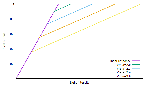
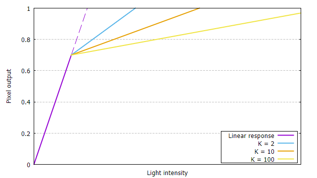
In HDR mode, the pixel response is based on a piecewise linear compression curve. A light intensity range of up to 100dB is mapped to 8-bit output values.
The response curve is controlled by the following parameters:
The following diagrams illustrate the responsivity curves for one knee point:


The maximum dynamic range is achieved with Vrsta = 3 and K = 500.
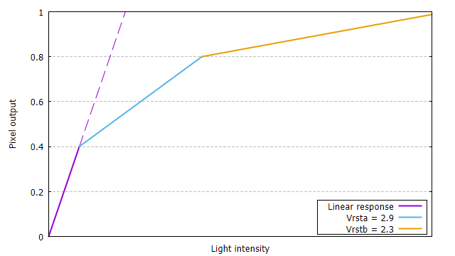
If two knee points are used, the parameter Vrstb determines the position of the second knee point. The value of Vrstb must be less than Vrsta:

In order to use HDR mode, the number of knee points must be configured before the first buffer is allocated, see special feature HDR_Mode below. The other parameters may be changed during acquisition.
| Property name | Description |
|---|---|
| HDR_Mode | 0: Linear mode (default) 1: HDR mode with one knee point 2: HDR mode with two knee points
|
| HDR_K | 1 ... 500: Compression factor |
| HDR_Vrsta | Position of the first knee point 1800 ... 3000: the desired float value (1.8 ... 3.0) multiplied by 1000 |
| HDR_Vrstb | Position of the second knee point 1800 ... 3000: the desired float value (1.8 ... 3.0) multiplied by 1000 |
Choosing a smaller AOI height will increase the maximum frame rate significantly. This makes the sensor also suitable for line scan applications.
A dedicated line scan mode was introduced which provides the following benefits:
A sensor scan height greater than one can be useful to increase the effective line rate. For example, an AOI size of 2048 x 4 allows a scan rate of 28 kHz which results in an effective line rate of 112 kHz.
Line scan mode is enabled by configuring the AOI with FG_set_scan_param() instead of FG_set_aoi(). The parameter image_scan_count specifies the number of sensor frames that will be concatenated into the larger destination image. A value of 1 disables line scan mode.
Example:
The following example configures a scan AOI of 1024 x 4 at the sensor's center location:
In line scan mode with hardware or software trigger enabled, each trigger event will start acquisition of one sensor frame containing the configured sensor scan height number of lines. The scan height acts like a trigger multiplier for the effective line rate. Multiple trigger events are required before the image is complete and returned to the user.
The RTCC can be used to adapt the the trigger signal to the desired scan rate, see Hardware trigger for examples.